Electronic Input
Devices
Electronic input devices are components or systems that enable the transfer of data or commands from the physical world into electronic systems. These devices play a crucial role in various applications, from simple button presses on a keyboard to complex sensor readings in environmental monitoring systems. Input devices detect and convert different forms of physical stimuli, such as touch, light, sound, or motion, into electrical signals that can be processed by electronic circuits or microcontrollers. Examples of electronic input devices include buttons, switches, sensors (such as temperature sensors, proximity sensors, or accelerometers), keyboards, mice, microphones, cameras, and more. These devices facilitate interaction between humans and machines, allowing users to provide instructions, data, or feedback to electronic systems for processing, control, or analysis.

Capacitive Sensor Implementation:
To create a capacitive sensor with a microcontroller, we'll utilize a technique known as capacitive sensing. Capacitive sensing relies on the principle that the capacitance of an electrode changes when it is brought close to a conductive object, such as a human finger. We'll measure this change in capacitance to detect proximity or touch.
Components Required:
- Microcontroller
- Capacitive sensing electrode
- Resistors (for pull-up or pull-down configuration)
Resistive Soil Moisture Sensor:
Resistive soil moisture sensors operate on the principle that the electrical resistance of the sensor changes with the amount of water present in the soil. Here's how they typically work:
A resistive soil moisture sensor usually consists of two or more metallic electrodes embedded in a porous material such as ceramic or gypsum. The porous material allows water to penetrate and come into contact with the electrodes.
When the soil is dry, the electrical resistance between the electrodes is high because water, being a good conductor, is absent or minimal. As the soil moisture increases, more water comes into contact with the electrodes, decreasing the resistance between them.
To calibrate a resistive soil moisture sensor, you would typically measure its resistance at different moisture levels: dry, moist, and wet. By correlating these resistance values with actual soil moisture levels, you can establish a calibration curve or equation.
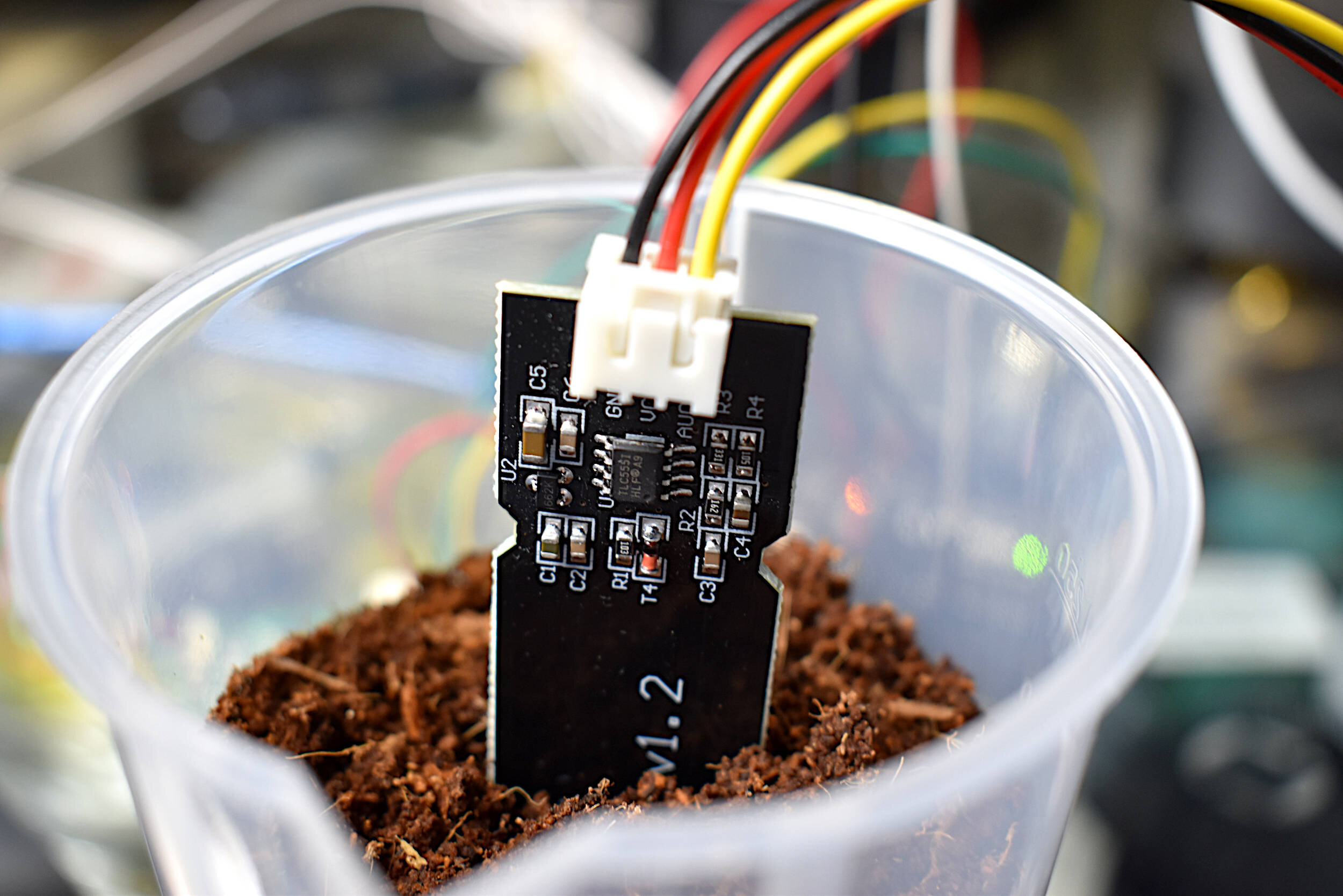
Capacitive Soil Moisture Sensor:
Capacitive soil moisture sensors measure the dielectric constant of the soil, which changes with varying moisture content. Here's how they generally work:
A capacitive soil moisture sensor typically consists of two conductive plates separated by a dielectric material (the soil). When the soil is dry, it has a lower dielectric constant, resulting in lower capacitance between the plates. As the soil moisture increases, the dielectric constant of the soil increases, leading to higher capacitance.
The probe of a capacitive soil moisture sensor usually includes electrodes or plates that are buried in the soil. These electrodes interact with the soil's dielectric properties to measure capacitance.
Calibration of a capacitive soil moisture sensor involves measuring its capacitance at different moisture levels and correlating these values with actual soil moisture content. This calibration process helps establish a relationship between sensor output (capacitance) and soil moisture levels.
Adding Soil Moisture Sensor and LED Output:
Let's incorporate a soil moisture sensor to measure soil moisture levels. We'll use an LED as an output device to indicate the moisture leve
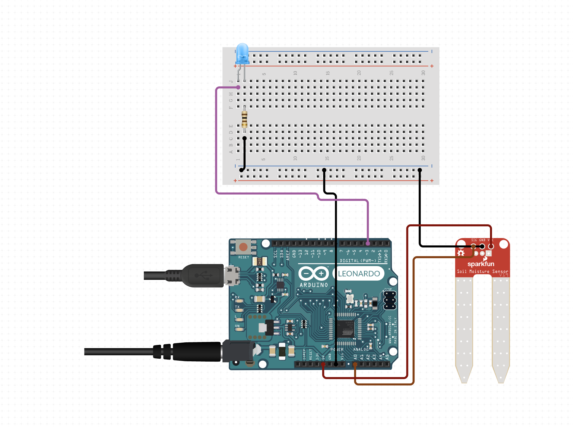
added from internet as i did not have the photo
Calibration and Signal Relationship:
For calibration, you would typically collect data points by varying the physical quantity being measured (e.g., soil moisture levels) and recording corresponding sensor readings. By plotting these points on a graph, you can observe the relationship between the sensor readings and the physical quantity.
For soil moisture sensors, the relationship between the sensor reading (analog value) and the actual moisture content in the soil is usually nonlinear. Initially, you might measure soil moisture at various levels (dry, moist, wet) and plot these points. Then, you can use techniques like curve fitting to establish a mathematical relationship between the sensor readings and the actual moisture content.
Similarly, for capacitive sensors, the relationship between the measured capacitance and the proximity of an object is nonlinear and depends on various factors like sensor design and environment. Calibrating by measuring capacitance at different distances from the sensor can help understand this relationship better.
/>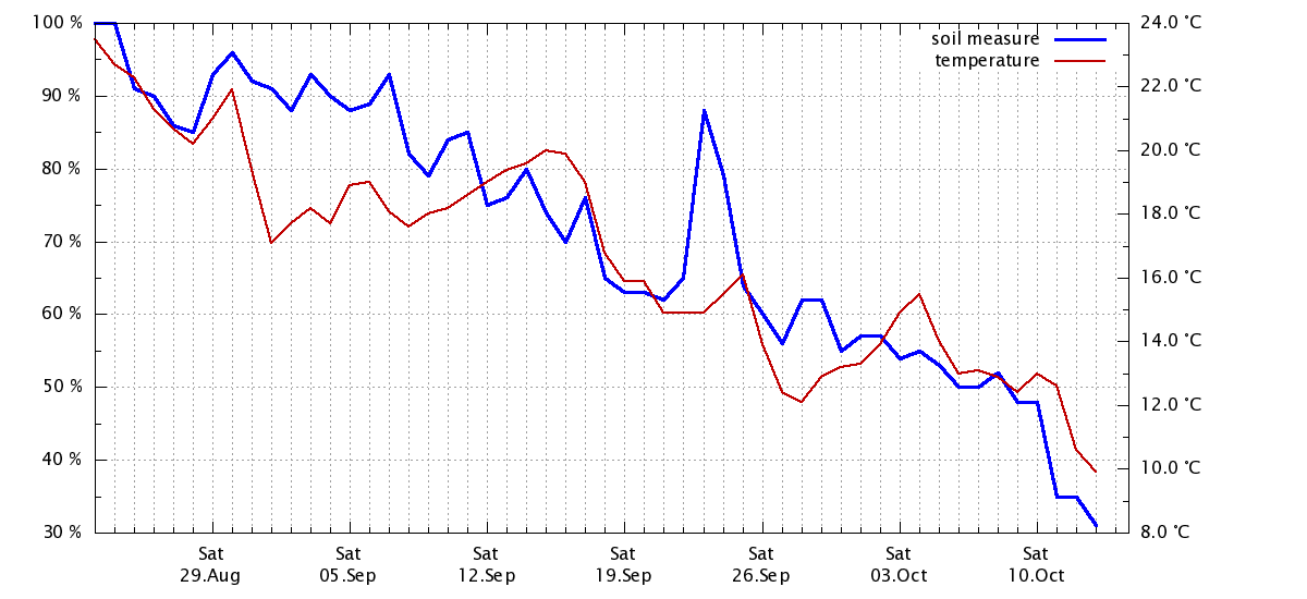
After throughly validation my code and after doing research i found how i can infuse puthon to creatae the graphs above, I gave my best in reaing and data structring those file but after i watched a youtube turuorial i came up with my own gragh which was totally uneven so i added the other graph
Comparison
Sensitivity: Capacitive soil moisture sensors are generally more sensitive to changes in soil moisture compared to resistive sensors. They can detect small variations in moisture content.
Corrosion Resistance: Capacitive sensors are often more resistant to corrosion because they don't rely on direct contact with the soil for measurement, unlike resistive sensors.
Calibration: Both types of sensors require calibration to establish accurate relationships between sensor readings and soil moisture levels. Calibration ensures that the sensor output corresponds reliably to actual soil conditions.
Article used to understand
Summary
In summary, resistive and capacitive soil moisture sensors offer different measurement principles and characteristics, but both are valuable tools for monitoring soil moisture levels in various applications. The choice between them depends on factors such as sensitivity requirements, environmental conditions, and cost considerations.