CNC
Machining
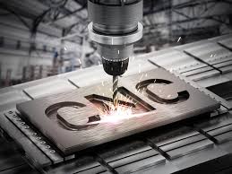
CNC (Computer Numerical Control) wood machine is a high-tech tool used in woodworking to precisely cut, carve, and shape wood according to digital designs. It operates by interpreting computer-generated codes to control the movement of its cutting tools along multiple axes, allowing for intricate and accurate woodworking tasks. CNC wood machines come in various sizes and configurations, from small desktop models suitable for hobbyists to large industrial-grade machines used in manufacturing. These machines have revolutionized woodworking by enabling automation, repeatability, and the production of complex designs with efficiency and precision.
Converting Jpeg To dxf
Converting a JPEG image to a DXF (Drawing Exchange Format) file using Inkscape involves several steps. Here's a detailed process:
Prepare your JPEG image: Before starting the conversion process, ensure that the JPEG image you want to convert to DXF is clear, high-resolution, and contains the necessary details you want to retain in the final vector graphic.
Install and launch Inkscape: If you haven't already installed Inkscape, download and install it from the official website. Once installed, launch the application on your computer.
Import the JPEG image: In Inkscape, go to the "File" menu and select "Import." Navigate to the location of your JPEG image on your computer and select it to import it into Inkscape. The JPEG image will appear on the canvas.
Prepare the JPEG image for tracing (optional): Before tracing the JPEG image, you may want to clean it up or adjust its size, position, or orientation on the canvas. Use the tools available in Inkscape, such as the "Selection" tool and the "Transform" options, to make any necessary adjustments.
Trace the bitmap: With the JPEG image selected on the canvas, go to the "Path" menu and select "Trace Bitmap." This will open the "Trace Bitmap" dialog box, where you can adjust the settings for the tracing process.
Adjust tracing settings: In the "Trace Bitmap" dialog box, you can customize the settings to control how Inkscape traces the bitmap image. You can choose between different tracing methods (such as "Brightness Cutoff" or "Edge Detection") and adjust parameters like threshold, smoothness, and color quantization to achieve the desired result.
Preview the trace: After adjusting the settings, click the "Update" button to generate a preview of the traced image. Take a moment to review the preview and make sure it accurately captures the details of the original JPEG image.
Fine-tune settings (if necessary): If the preview doesn't meet your expectations or if you want to further refine the tracing result, you can go back and adjust the tracing settings accordingly. Experiment with different settings until you're satisfied with the outcome.
Apply the trace: Once you're happy with the preview, click the "OK" button in the "Trace Bitmap" dialog box to apply the tracing settings and close the dialog box. Inkscape will convert the JPEG image into a vector graphic based on your chosen settings.
Save the vector graphic as a DXF file: With the traced vector graphic selected on the canvas, go to the "File" menu and choose "Save As." In the "Save as type" dropdown menu, select "Desktop Cutting Plotter (AutoCAD DXF)" as the file format. Choose a location on your computer to save the DXF file, enter a filename, and click the "Save" button.
Review the DXF file: After saving the DXF file, open it in a compatible CAD software to verify that the conversion was successful and that the vector graphic retains the necessary details and accuracy.
By following these detailed steps, you should be able to effectively convert a JPEG image to a DXF file using Inkscape while maintaining control over the tracing process and achieving the desired result.
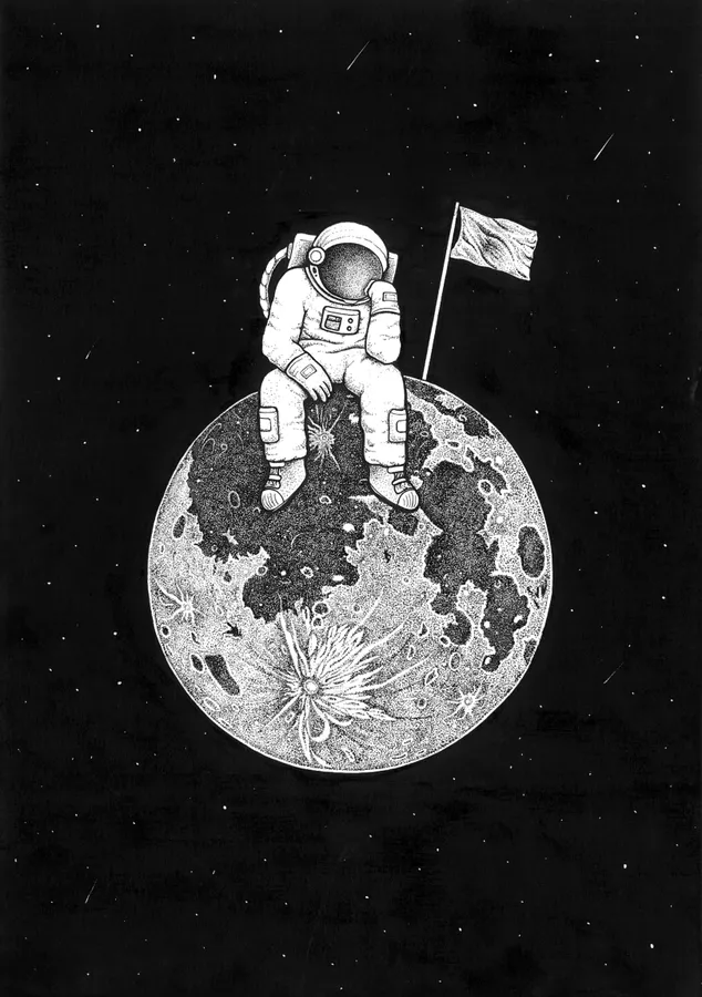
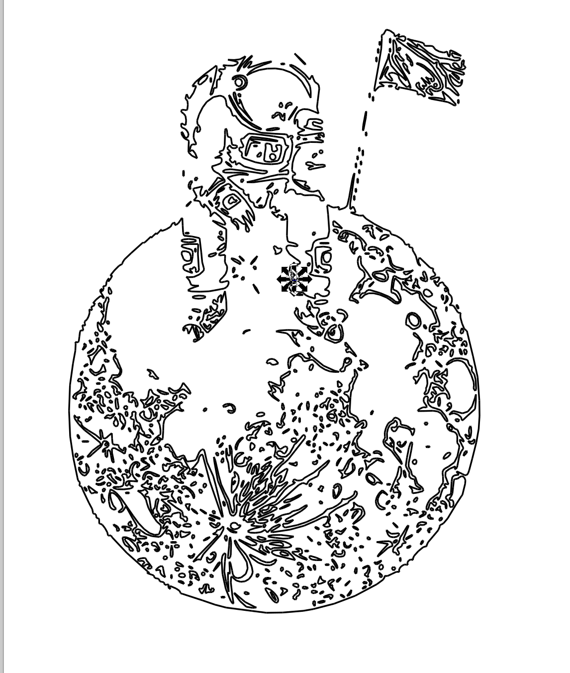
Image2Surface
Image to Surface is a software designed for converting raster images, such as JPEGs, into 3D surfaces or relief models. This specialized tool is particularly useful in various fields like woodworking, CNC machining, and 3D printing, where translating 2D images into three-dimensional objects is essential. The software employs advanced algorithms to analyze the pixels of the image and generate a corresponding height map or relief model, capturing intricate details and contours. Users can adjust parameters such as resolution, scaling, and depth to tailor the output to their specific requirements. The resulting 3D surface can then be exported in various formats suitable for further processing or manufacturing. This software streamlines the conversion process, enabling users to create accurate and detailed 3D representations from raster images with ease.
To install the Image2Surface add-in for Fusion 360, begin by downloading the ZIP archive from GitHub. Navigate to the GitHub repository and click on the "Clone or download" button, then select "Download ZIP." Once the ZIP file is downloaded, unarchive it into the Addins folder. After unarchiving, rename the created folder from "Fusion360Image2Surface-master.zip" to "Image2Surface." This folder should now contain the necessary files for the add-in.
Next, open Fusion 360 and access the Scripts and Add-Ins Manager. Here, you can add the Image2Surface folder to Fusion 360. If you want the add-in to automatically start when Fusion 360 starts up, select the "Run on Startup" checkbox. This option is convenient for frequent use of the add-in.
When you run the Image2Surface add-in for the first time, it will add itself to the Add-ins panel dropdown of the Model environment. You should see an entry labeled "Show Image 2 Surface."
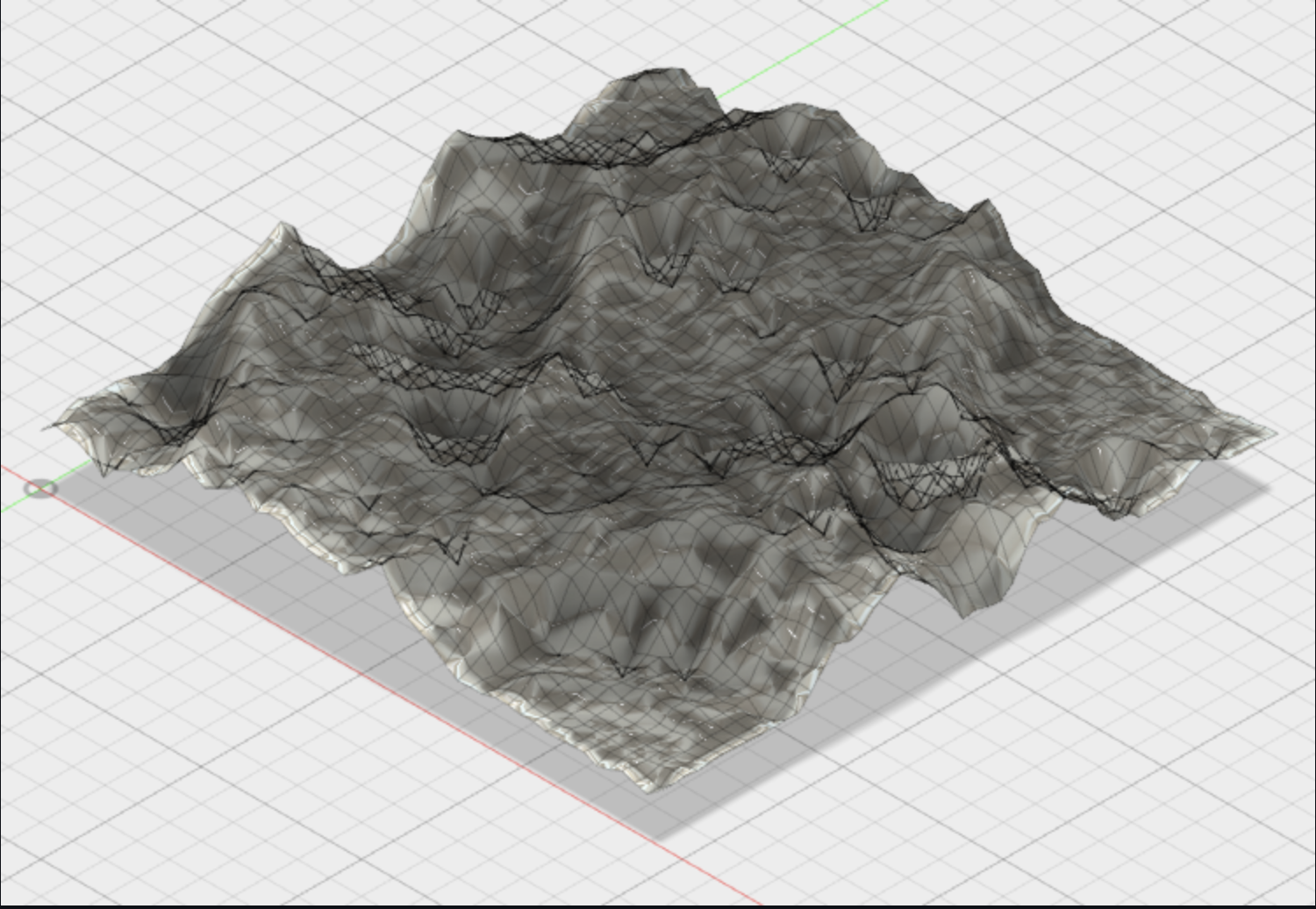
To use the add-in, ensure that your document is in parametric modeling mode. Enter the Model environment and run the Image2Surface add-in from the Scripts and Add-Ins Manager. The add-in will display the Image 2 Surface Palette, where you can preview the surface mesh that will be generated and adjust mesh parameters.
You can select an image file by dragging and dropping it onto the palette window or by clicking the "Open Image File" button. However, note that overly large images may cause problems or even crash the application, so it's recommended to work with images under 1000x1000 pixels initially.
After loading the image, you can preview the surface mesh and adjust the view using mouse controls. Additionally, you can fine-tune mesh parameters such as Pixels to Skip, Stepover, Max Height, Invert Heights, Smooth, and Absolute (B&W) to customize the mesh generation process.
Once you're satisfied with the settings, click the "Generate Surface" button to create the mesh within the active document. You may need to "fit" the view to see the generated mesh.
Finally, if you wish to further modify the mesh, you can convert it to a T-Spline or BREP. Click on the "Create Form" button to enter the Sculpt environment for T-Spline conversion, or select the mesh and use the Mesh to BRep option in the Model environment for BREP conversion.
Ensure that the add-in files are placed in their own folder within the Addins folder to prevent Fusion 360 from failing to load the add-in. Additionally, be cautious with large images, as they can create large meshes that may cause Fusion 360 to take a long time to process or even fail.
Casting And Modelling
Casting and molding are fundamental processes in manufacturing and prototyping, offering versatile methods for creating complex shapes and structures. Casting involves pouring a liquid material, typically molten metal or plastic resin, into a mold cavity, where it solidifies into the desired shape. Molding, on the other hand, encompasses various techniques for shaping materials, such as clay, silicone, or plastic, by pressing them into a mold or form.
In casting, the mold plays a crucial role in defining the final shape and surface finish of the cast part. Depending on the material being cast and the desired outcome, molds can be made from materials like sand, plaster, silicone, or metal. Each casting material and mold type has its own advantages and limitations, influencing factors such as cost, complexity, and durability.
The casting process typically involves several steps:
Pattern or Model Creation: Before casting can begin, a pattern or model of the desired part is created. This pattern can be made from various materials, including wood, metal, or 3D-printed plastic.
Mold Making: The pattern is used to create a mold, which is a negative impression of the desired part. The mold can be made from materials such as sand, silicone, or metal, depending on the casting method and material being used.
Melting and Pouring: The casting material, such as molten metal or liquid resin, is melted and then poured into the mold cavity. Care must be taken to ensure proper temperature control and material flow to achieve the desired results.
Cooling and Solidification: Once the material has been poured into the mold, it is allowed to cool and solidify. This process may take varying amounts of time depending on the material and the size and complexity of the part being cast
Finishing: After the cast part has solidified, it may undergo additional finishing processes such as machining, sanding, or polishing to achieve the desired surface finish and dimensional accuracy.
Vaccum Forming
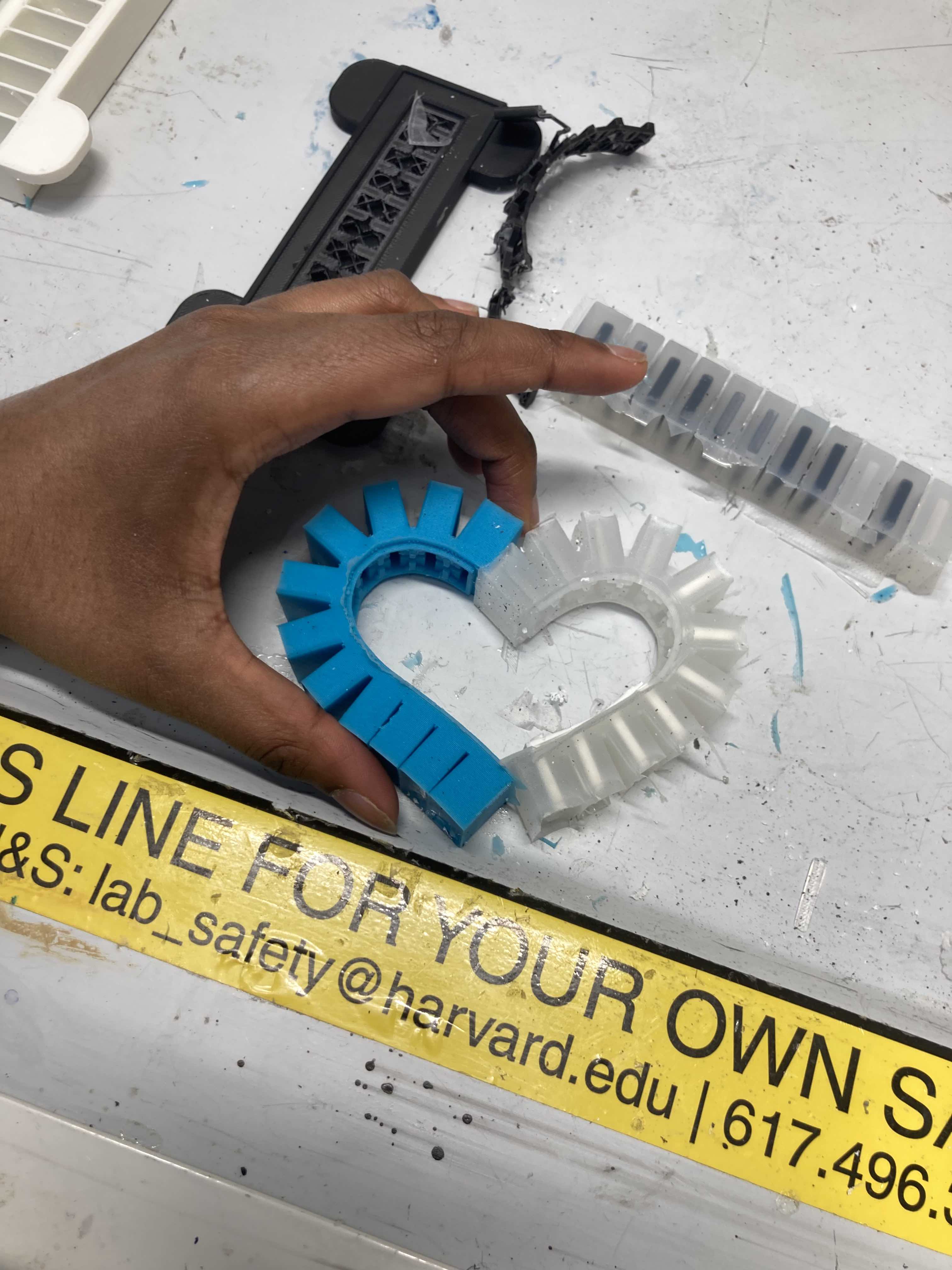
Vacuum forming is another popular technique for creating hollow plastic parts with complex shapes. In vacuum forming, a sheet of thermoplastic material is heated until it becomes soft and pliable, then stretched over a mold or form. A vacuum is applied to draw the heated plastic tightly against the mold, forming the desired shape. Once the plastic has cooled and hardened, the vacuum is released, and the formed part can be removed from the mold.
I had the opportunity to attend a workshop on modeling conducted by Conflux at Harvard, where we explored similar modeling techniques. Through hands-on experience, we learned about pattern making, mold creation, and casting processes, gaining insight into the intricacies of translating designs into physical objects. This practical experience reinforced the importance of understanding materials, processes, and design considerations when working with casting and molding techniques.