Final
Project
Title: Self Leveling Drone
Description:
.In today's ever-evolving technological landscape, drones have emerged as indispensable tools in various fields, from aerial photography to package delivery. Among the myriad applications, one area that stands out is precision agriculture, where drones equipped with sensors offer invaluable insights into crop health, soil moisture, and other vital metrics. However, ensuring optimal performance and efficiency in agricultural drone operations often demands precise control over altitude, particularly in terrain with varying elevations. This is where the innovation of a self-leveling drone using Arduino enters the picture, offering a game-changing solution to elevate agricultural practices to new heights.
Importance of self leveling drone
The significance of a self-leveling drone lies in its ability to maintain a stable and consistent altitude autonomously, even in challenging environments. In agriculture, where efficiency and accuracy are paramount, such a capability can revolutionize farming practices. By ensuring the drone maintains a constant height above ground level, regardless of changes in terrain, farmers can obtain more accurate data about their fields. This enables them to make data-driven decisions regarding irrigation, fertilization, pest control, and overall crop management, leading to improved yields and resource utilization.
Mention of Step-by-Step Instructions and Learning:
Having embarked on the journey of developing a self-leveling drone using Arduino, I have gained invaluable insights and experiences. Through meticulous experimentation and iteration, I have honed my skills in electronics, programming, and drone mechanics. Step by step, I have navigated through the intricacies of sensor integration, control algorithms, and flight dynamics, overcoming challenges and embracing the learning opportunities they presented. Moreover, by documenting my process and sharing detailed instructions, I aim to contribute to the collective knowledge base and inspire others to explore the possibilities of drone technology in agriculture and beyond.
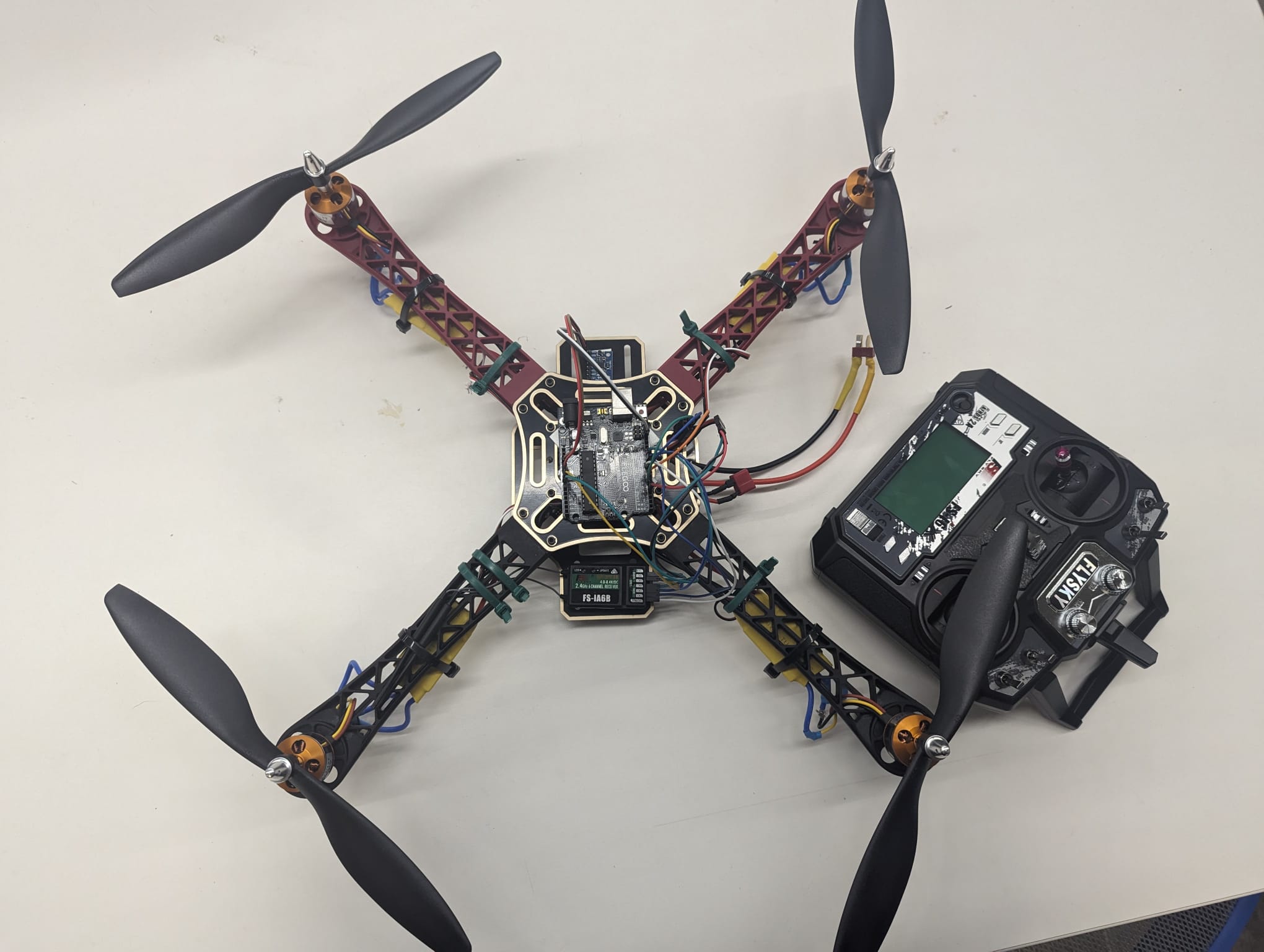
Hardware
I often get the question what hardware is needed to build the YMFC-AL quadcopter. I made the following hardware list for your convenience. This list is a suggestion and it's your own responsibility to ensure that the products meet your specific requirements. But this list should be sufficient to build the YMFC-AL quadcopter.
- 1 x 450 size frame with integrated power distribution board
- 4 x 1000kV motor / 10x4.5 props / ESC combo/li>
- 1 x 3S / 2200mAh / 20C lipo
- 1 x Arduino Uno
- 1 x MPU-6050 gyro / accelerometer
- 1 x Flysky FS-i6 6-CH TX Transmitter
- 1 x 2S/3S lipo battery charger
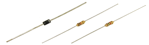
And some small parts like three resistors (1.5kΩ & 1kΩ & 330Ω), a 1A diode (1N4001 or similar), LED, some wire, a connector for the flight battery, etc.
I personally prefer (and use) 8x4.5 inch props instead of the 10x4.5 inch props. This to offload the motors and ESC's and to get a better response.
Article used to understand
- MPU-6050 6dof IMU for auto-leveling multicopters
- Milling Carbon Fiber
- Reviving a Clone Basecam brushless gimbal controller
- Electromagnetic interference in relation to multicopters
1 The build
1.1 The diode D1 and resistors R2 / R3
The diode D1 protects the USB port of the computer when the Arduino is connected to the computer. This diode has an important function and cannot be excluded.
The resistors divide the flight battery voltage by 2.5. This way it is possible to measure the battery voltage during flight. The LED will light up when the battery voltage gets to low and the motor rpm automatically increase to compensate the dropping battery voltage during flight.
The 1kΩ and 1.5kΩ resistors need to be installed correctly otherwise the quadcopter will not fly perfect.
1.2The MPU-6050 gyro/accelerometer
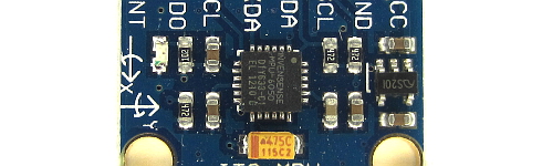
The only gyro / accelerometer that is supported by the software is the MPU-6050. This is because the auto-level feature requires an accelerometer and a gyro
The orientation of the gyro is not important as long as the Z-axis is vertical (perpendicular to the surface) and the edges of the gyro are aligned with the edges of the quadcopter. Click on the image to see all the possible gyro orientations.
The setup software will detect the gyro's orientation and invert the gyro and accelerometer axis when necessary. Mount the gyro with thin double side tape. Don't use foam tape or other dampening material. This will decrease the performance.
1.3The tranmitter and receiver
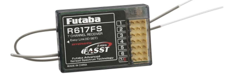
Almost every 4 channel RC transmitter can be used for the YMFC-AL. The most important feature is the used receiver output pulse. The range should be approximately 1000 till 2000 with a 1500 center position.
Connect the roll (aileron), pitch (elevator), yaw (rudder) and throttle output of the receiver to the Arduino Uno ports 8, 9, 10 and 11. The order is not important as the setup software will recognize each separate channel. Check the manual of the transmitter / receiver to see which receiver port is connected to the specific function.
The receiver is powered by the +5V output of the Arduino. The connection can be found on the schematic (top left corner 'Receiver power').
1.4The ESC's
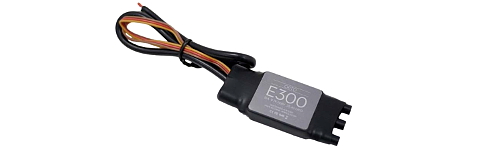
On the schematic only the ground and the signal wires of the ESC's are connected. This is correct. The +5V from the ESC is not connected because the Arduino gets its power directly from the flight battery via the diode D1.
In some cases the ground of the ESC doesn't have to be connected. Check with a multimeter if the ground of the battery connection is connected to the ground / - of the esc connection wire. If these are connected the ground of the ESC does not need to be connected to the Arduino because they share the same battery ground.
The signal wire of the ESC's are connected to the digital outputs 4, 5, 6 and 7 of the Arduino as shown in the table below. Also check the direction of rotation.
| Arduino | Location | Direction of Rotation |
|---|---|---|
| D4 | right front | counter clockwise |
| D5 | right rear | clock wise |
| D6 | left rear | counter clock wise |
| D7 | left front | clockwise |
2 Run the setup software
Remove the props, don't connect the flight battery and upload the setup program to the Arduino Uno. Open the serial monitor at 57600baud and complete the setup by executing the requested actions.
After the setup is completed all the settings are stored in the EEPROM of the Arduino.
2.1 No valid receiver signals found.
At startup the setup software is detecting valid receiver pulses on digital inputs 8, 9, 10 and 11. A pulse is valid when it is longer than 900 and shorter than 2100 microseconds.
Solution :
- The receiver outputs: roll/aileron, pitch/elevator, yaw/rudder and throttle need to be connected to the digital inputs 8, 9, 10 and 11. The order is not important.
- Make sure that the receiver is correctly connected / bound with the transmitter.
- Turn on the transmitter
2.2 No stick movement detected in the last 30 seconds.
At some point the setup software request the user to move the stick that corresponds with the specific quadcopter action. The setup software scans the digital inputs to check if there is a change in pulse length.
A valid movement is detected when the pulse is longer than 1750 or shorter than 1250 microseconds.
2.3 No gyro device found.
The setup software cannot get a valid Who_am_I reaction from the gyro. The setup software searches for the gyro's: MPU-6050 on address 0x68/104 and 0x69/105; L3G4200D on address 0x68/104 and 0x69/105; L3GD20H on address 0x6A/106 and 0x6B/107; During detection the setup software requests a Who_am_I reaction. If the gyro does not response or the Who_am_I value is incorrect the error message appears.
Check if the gyro is connected correctly to the Arduino Uno. Arduino Gyro GND - GND 5V - Vin/VCC SDA/A4 - SDA SCL/A5 - SCL 2)Make sure that the gyro Is 5V compatible. Otherwise the gyro needs to be connected to 3.3V and a level converter should be used.
2.4 No angular motion is detected in the last 10 seconds.
At some point the setup software requests the user to move the quadcopter in a specific 45 degree angle within 10 seconds. During this action the setup software is following the movements of the quadcopter. When an angle of more than 30 degree is detected the specific gyro axis is connected to the specific function.
When the 30 degree is not reached or the time is expired the error message will appear.
2.5 EEPROM verification failed.
All the data that is collected during setup is stored in the EEPROM of the Arduino Uno (ATmega328P). When the EEPROM writing is done the written EEPROM data is checked. When there is a difference between the EEPROM and the collected data during setup this error message appears.
Code for the setup
/>3 Receiver and gyro check
To make sure that everything is working correct it's necessary to run some basic checks. Remove the props, disconnect the flight battery and upload the ESC calibration program to the Arduino. Open the serial monitor at 57600baud.
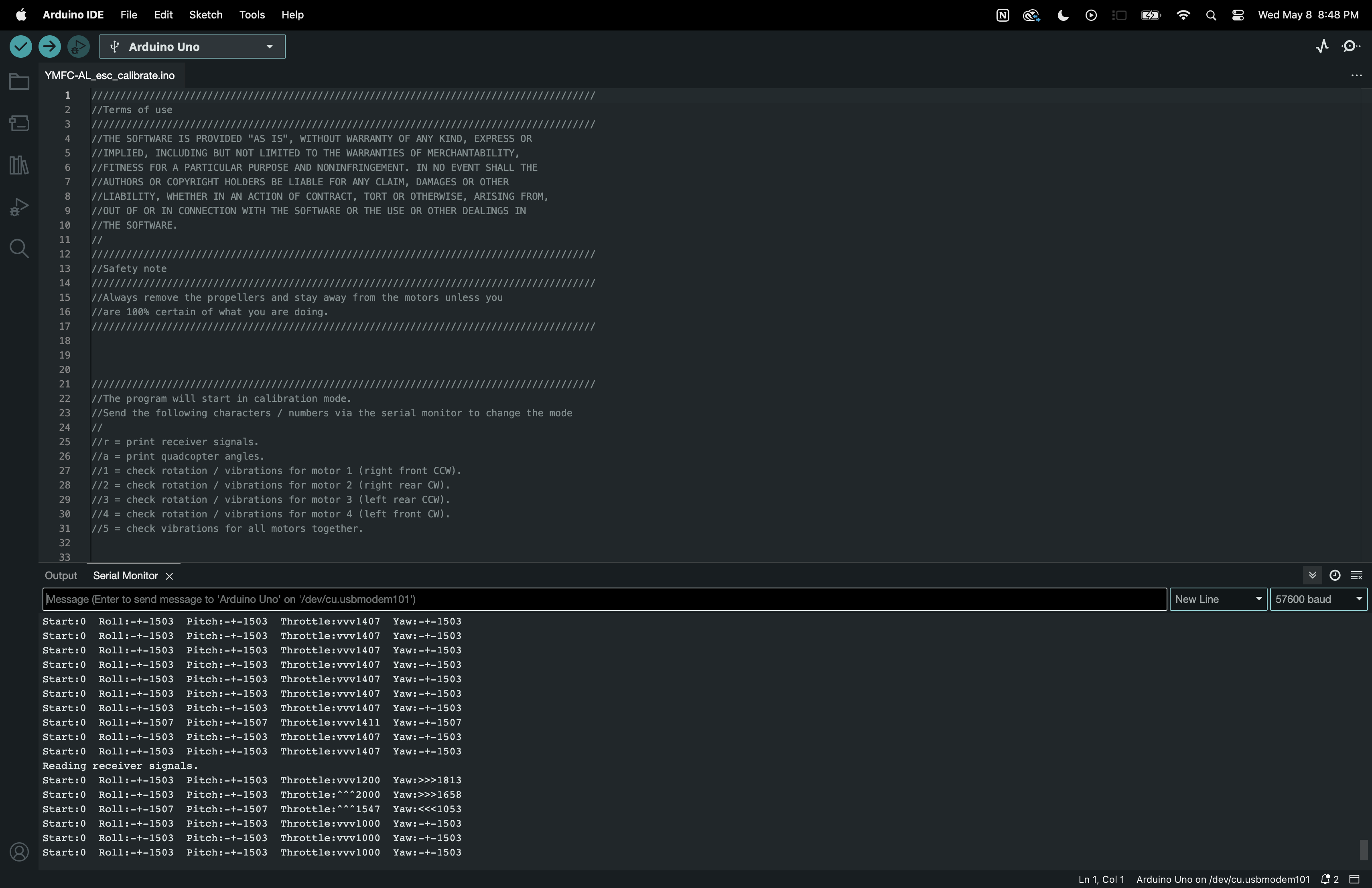
3.1 Receiver input check
Send the letter 'r' to start the receiver monitor. Now move the sticks and see if the values on the screen correspond with the movements of the sticks.
All the channels should read 1000us till 2000us with a center position of 1500 (+/-8).
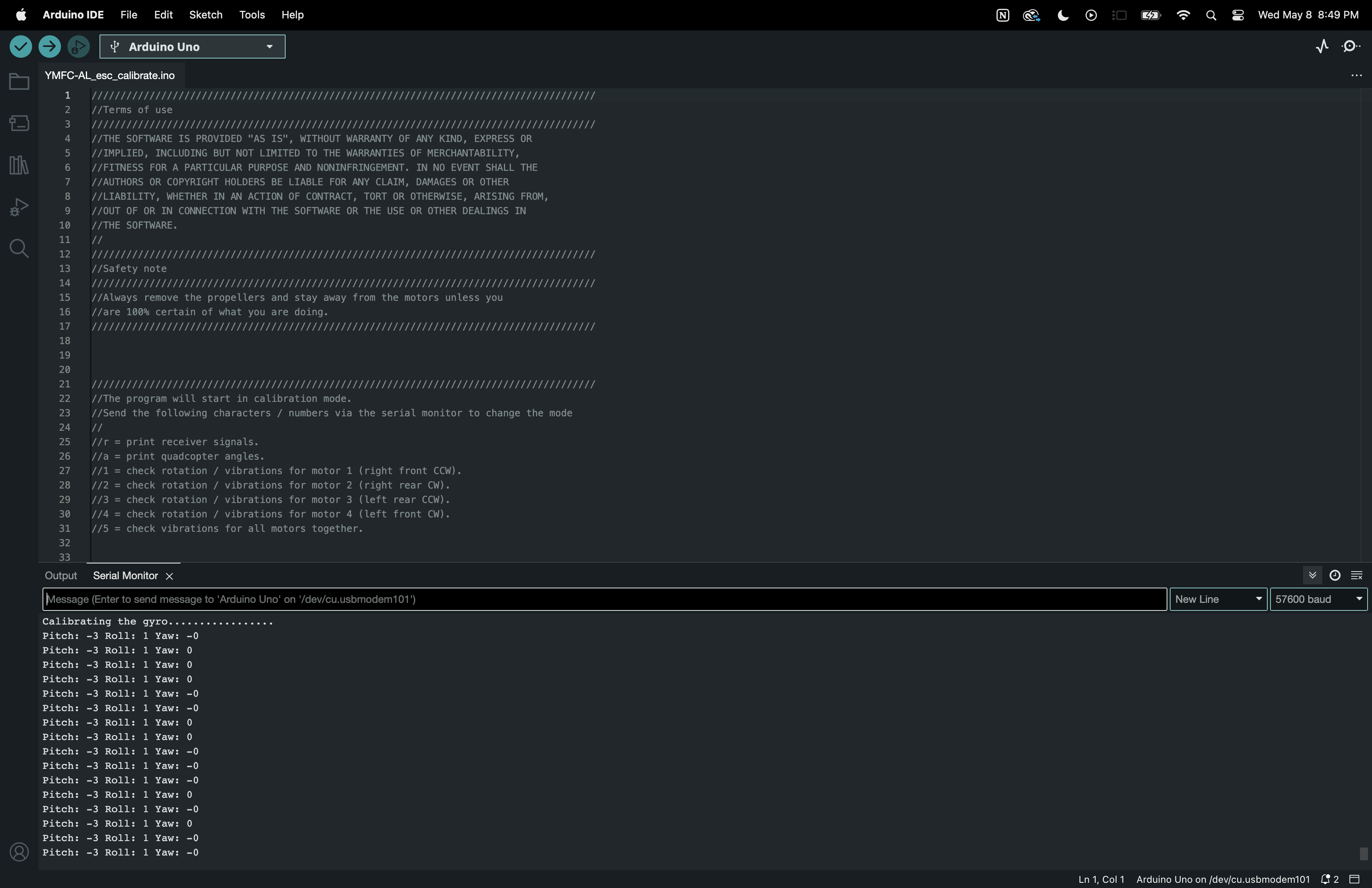
3.2 Gyro / accelerometer angle check
After the receiver check is completed send the letter 'a' to start the angle check
Don't move the quadcopter because the gyro needs to calibrate itself. After the calibration the roll and pitch angles are shown. The yaw value is the output of the gyro and will go back to zero if the yaw rotation stops.
Check if the angles correspond with the movement of the quadcopter:
- Nose up is positive pitch and nose down is negative pitch.
- Left wing up is positive roll and left wing down is negative roll
- Nose right is positive yaw and nose left is negative yaw.

4 Calibrate the ESC's
Electronic speed controllers or ESC's for short are controlled with a 1000us till 2000us pulse. 1000us means off and 2000us means full throttle. To make sure that all the ESC's react the same way it's important to calibrate the 1000us and 2000us point. Without calibration the motors will perform different and the quadcopter doesnt fly well or might even crash.
Remove the props and upload the ESC calibration program to the Arduino. Disconnect the USB cable and follow the instructions in the manual to calibrate the ESC's.
In most cases this is done with the following steps: Place the throttle stick in the upper position (full throttle) Connect the flight battery After some beeps place the throttle stick in the lowest position Disconnect the flight battery
Code for Callibrating ECS
5 balance the motors and props
SAFETY NOTE: This is the first time that the motors will run with the mounted props. Make sure that a save operation is possible
5.1 Why is balancing the props important?
Balancing the props is incredibly important! Without well balanced props and motors the gyro and accelerometer will produce noise that makes the motors react jerky. There is minimal stability and the quadcopter can't level itself.
To get the best performance the props and motors need to be balanced perfectly. Putting the gyro / accelerometer on vibration dampeners does not help and can only make things worse.
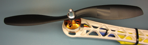
5.2 How to balance the props
Mount the props on the motors and check if the counter clock wise and clock wise props are in the right position. Upload the ESC calibration program and open the Arduino serial monitor at 57600baud. Send '1' via the serial monitor and wait for the response "Test motor 1 (right front CCW.)".
The numbers that are printed on the screen represents the amount of vibration measured by the accelerometer. This is not a standardized value and should only be used to minimize the amount of vibration of your YMFC-AL quadcopter.
Hold the quadcopter firmly down, place the throttle in the lowest position and connect the flight battery. Now slowly increase the throttle until motor 1 starts to spin. Check the direction of rotation and that the prop produces upward thrust. If the motor rotates in the wrong direction you need to switch two of the three motor wires. Put the throttle in the lowest position to stop the motor.
Now hold the motor frame firmly in your hand and increase the throttle to half throttle. Check the numbers on the screen and also memorize the vibrations that you feel with you hand that is holding the motor frame.
Stop the motor and put a small piece of tape on one of the blades and run the test again. Check if the vibrations reduce. If nor try a piece of tape on the other blade. Keep doing this until the motor and prop run as smooth as possible. This can sometimes be a daunting task but the reward is a very stable flying quadcopter. So take your time and get it perfect!
When done with motor 1, send a '2' via the Arduino IDE and start the process again for motor / prop 2. And after that, send a '3' for motor number 3 and a '4' for motor 4.
By sending a '5' all the motors will run together as a final test.
6 Upload the flight controller software
Disconnect the flight battery and upload the flight controller software to the Arduino. Disconnect the USB cable and connect the flight battery
Hold the quadcopter firmly in your hand and start the motors with the following sequence:
Start = throttle down and yaw left
Stop = throttle down and yaw rigt
Increase the throttle up to the point when it almost starts to become weightless. The quadcopter should now try to level itself. If you move the quad it should start to counteract the movement until it is level again.
When the roll or pitch stick of the transmitter is moved the quadcopter should move in the same direction. If this is not the case redo the setup procedure and double check all the points on this page.
When all is good it is time for a careful first test flight. Always fly the quadcopter outdoor and over grass for safety. Grass will minimize the damage during a crash.
Code for Flight Controller Software
Final Output
Learnings and Conclusion
Interdisciplinary Skill Development
uilding a self-leveling drone demanded that I delve into various fields like electronics, programming, mechanics, and aerodynamics. Through this project, I gained hands-on experience in each domain, realizing how they intertwine to create complex systems and solutions.
Problem-Solving and Iterative Design:
Creating a functional self-leveling mechanism required constant problem-solving and iterative design. From tackling sensor calibration glitches to refining PID control algorithms, I learned the value of persistence, patience, and meticulous attention to detail in overcoming hurdles and refining performance.
Understanding Sensor Integration
Integrating sensors such as accelerometers, gyroscopes, and altimeters into the drone's control system was pivotal for precise altitude measurement and stabilization. Through experimentation and research, I deepened my understanding of sensor technologies and mastered their integration into the Arduino platform for real-time data processing.
Flight Dynamics and Stability:
Ensuring stable flight characteristics was paramount for the drone's safe and efficient operation. By studying flight dynamics principles and conducting numerous flight tests, I gained insights into factors influencing stability, such as center of gravity, thrust-to-weight ratio, and aerodynamic forces. This knowledge empowered me to fine-tune the drone's control system, maintaining consistent altitude and attitude during flight.
Documentation and Sharing Knowledge:
Documenting each step of the project and sharing detailed instructions not only solidified my own understanding but also served as a valuable resource for fellow enthusiasts. By articulating concepts, methodologies, and troubleshooting strategies, I not only enhanced my learning journey but also contributed to the wider maker community, fostering collaboration and innovation.
Future Goals:
Looking ahead, the future of self-leveling drones in agriculture is promising. As technology continues to advance, we can anticipate further enhancements in drone capabilities, such as integration with artificial intelligence for real-time data analysis and decision-making. Additionally, improvements in sensor technologies and communication systems will enable drones to gather and transmit data with even greater accuracy and efficiency. Ultimately, the goal is to empower farmers with the tools they need to maximize productivity while minimizing environmental impact, ushering in a new era of sustainable agriculture.