Minimum Viable
Project
Minimum Viable Project (MVP) is a streamlined and essential version of our envisioned product, designed to quickly validate our concept in the market with minimal resources. It focuses on delivering core functionalities that address key user needs, allowing us to gather valuable feedback and iterate efficiently. By prioritizing essential features and rapid development, our MVP serves as the foundation for future enhancements and ensures a lean and agile approach to product development.

Frame drone And Assemblibg
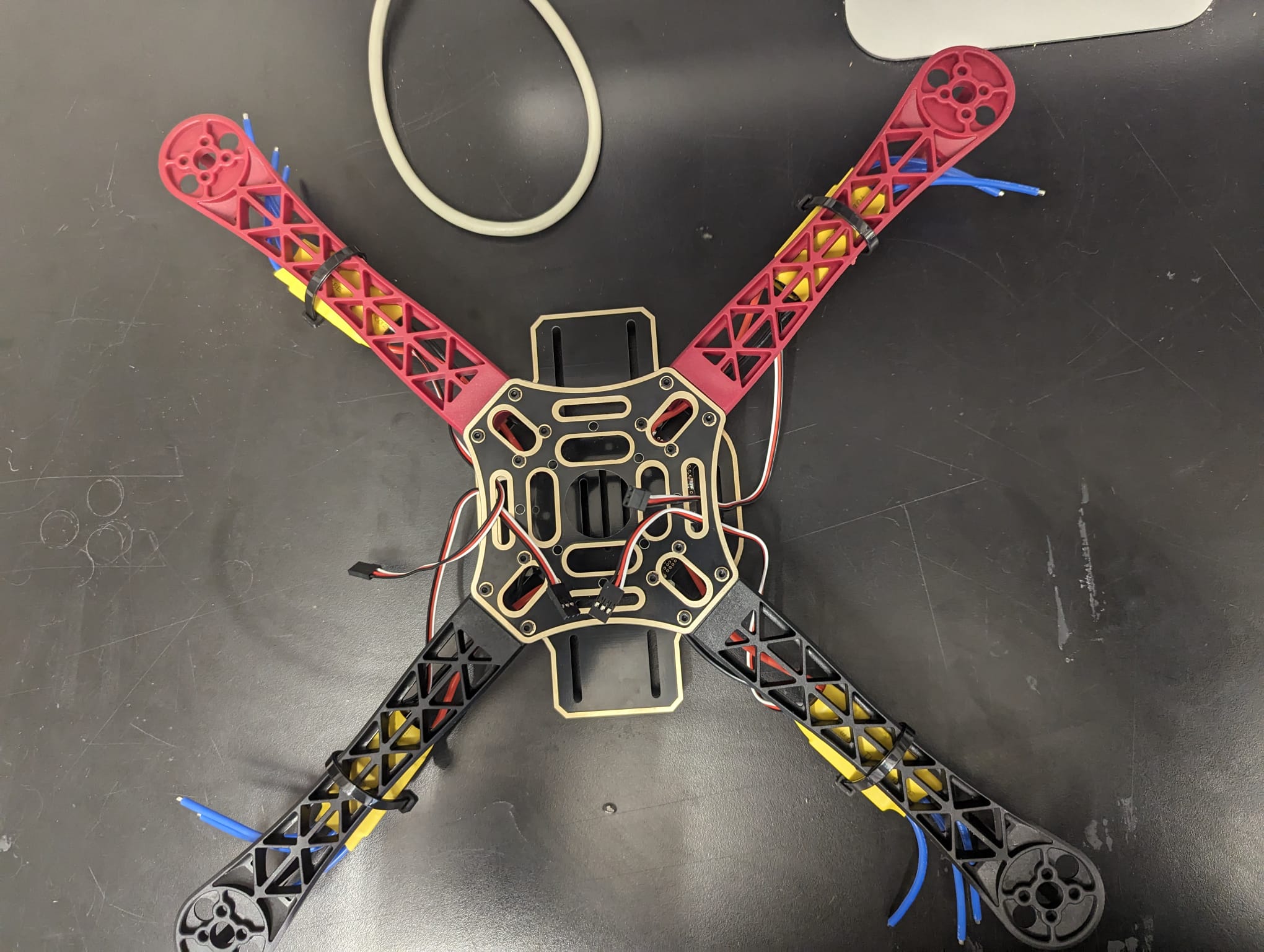
Creating a quadcopter involves careful consideration of its frame and power supply board, as these components play crucial roles in its stability, functionality, and overall performance.
The frame of the quadcopter serves as its structural backbone, providing support and stability to the various components attached to it. It must be lightweight yet durable to withstand the stresses and strains encountered during flight maneuvers. Additionally, the frame's design impacts the quadcopter's aerodynamics and maneuverability, influencing its agility and responsiveness in the air. Therefore, selecting the right frame is essential for optimizing the quadcopter's performance and ensuring a smooth and stable flight experience.
Equally important is the power supply board, which serves as the electrical hub of the quadcopter, distributing power from the battery to the various electronic components, including the motors, flight controller, and other onboard systems. The power supply board must be designed to handle the voltage and current requirements of these components efficiently, ensuring stable and reliable power distribution throughout the flight. Moreover, it should incorporate safety features such as overcurrent protection and voltage regulation to prevent damage to the quadcopter's electronics and ensure safe operation.

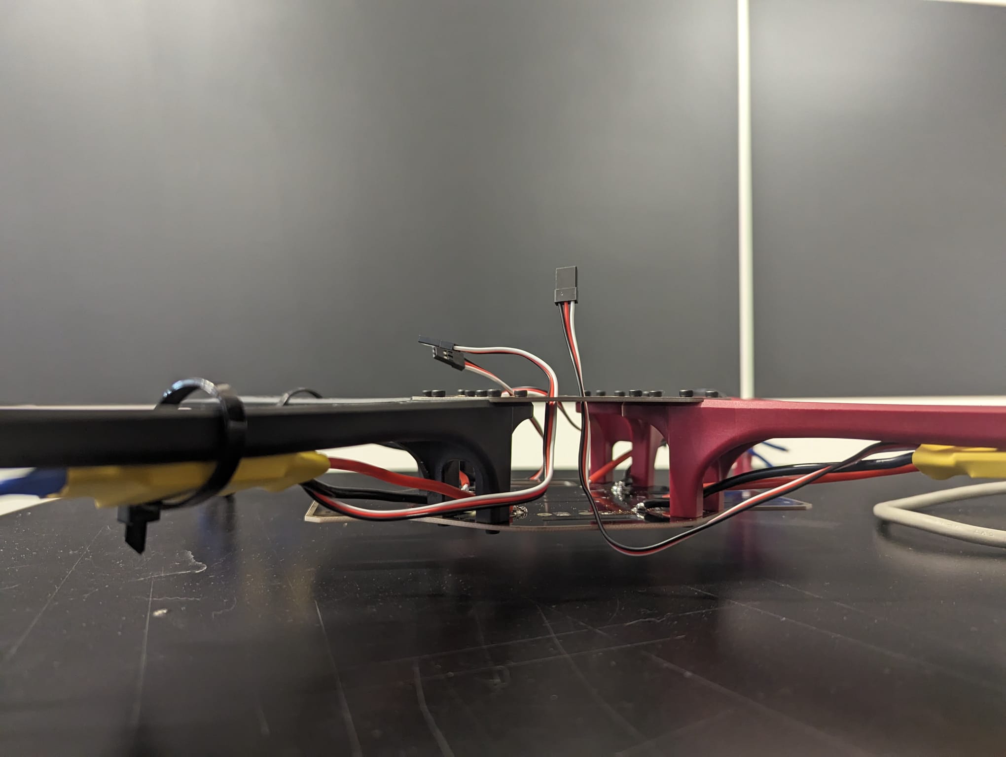
When assembling the power supply board, utmost care must be taken to ensure proper wiring and connections. Any mistakes or loose connections could lead to electrical issues, such as short circuits or power fluctuations, which can damage the quadcopter or cause it to malfunction mid-flight. Therefore, attention to detail and adherence to wiring diagrams and assembly instructions are critical to ensuring the reliability and safety of the power supply board.
Once the frame and power supply board are in place, the next step is to assemble the remaining drone parts, including the motors, propellers, flight controller, and electronic speed controllers (ESCs). Each component must be installed correctly and securely to ensure proper functionality and flight performance. Additionally, calibration and testing are essential steps to verify that all components are working together harmoniously and that the quadcopter is ready for flight.
Overall, careful attention to detail and precision in assembly are essential when building a quadcopter, particularly concerning the frame and power supply board. By selecting the right components and assembling them meticulously, you can ensure the reliability, stability, and safety of your quadcopter, laying the foundation for successful flights and future enhancements.
MPU-6050 6dof IMU for auto-leveling multicopters
Auto leveling a multicopter is pretty challenging. It means that when you release the pitch and roll controls on your transmitter the multicopter levels itself. To get this to work the flight controller of the multicopter needs to know exactly which way is down. Like a spirit level that is on top of the multicopter for the pitch and roll axis.
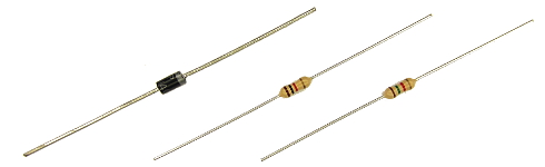
The diode D1 protects the USB port of the computer when the Arduino is connected to the computer. This diode has an important function and cannot be excluded.
The resistors divide the flight battery voltage by 2.5. This way it is possible to measure the battery voltage during flight. The LED will light up when the battery voltage gets to low and the motor rpm automatically increase to compensate the dropping battery voltage during flight.
The 1kΩ and 1.5kΩ resistors need to be installed correctly otherwise the quadcopter will not fly perfect.
1.2The MPU-6050 gyro/accelerometer
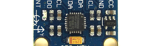
The only gyro / accelerometer that is supported by the software is the MPU-6050. This is because the auto-level feature requires an accelerometer and a gyro
The orientation of the gyro is not important as long as the Z-axis is vertical (perpendicular to the surface) and the edges of the gyro are aligned with the edges of the quadcopter. Click on the image to see all the possible gyro orientations.
The setup software will detect the gyro's orientation and invert the gyro and accelerometer axis when necessary. Mount the gyro with thin double side tape. Don't use foam tape or other dampening material. This will decrease the performance.
1.3The tranmitter and receiver
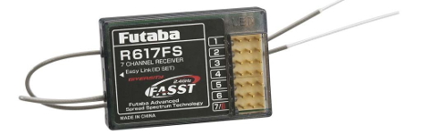
Almost every 4 channel RC transmitter can be used for the YMFC-AL. The most important feature is the used receiver output pulse. The range should be approximately 1000 till 2000 with a 1500 center position.
Connect the roll (aileron), pitch (elevator), yaw (rudder) and throttle output of the receiver to the Arduino Uno ports 8, 9, 10 and 11. The order is not important as the setup software will recognize each separate channel. Check the manual of the transmitter / receiver to see which receiver port is connected to the specific function.
The receiver is powered by the +5V output of the Arduino. The connection can be found on the schematic (top left corner 'Receiver power').
1.4The ESC's
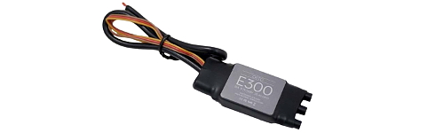
On the schematic only the ground and the signal wires of the ESC's are connected. This is correct. The +5V from the ESC is not connected because the Arduino gets its power directly from the flight battery via the diode D1.
In some cases the ground of the ESC doesn't have to be connected. Check with a multimeter if the ground of the battery connection is connected to the ground / - of the esc connection wire. If these are connected the ground of the ESC does not need to be connected to the Arduino because they share the same battery ground.
The signal wire of the ESC's are connected to the digital outputs 4, 5, 6 and 7 of the Arduino as shown in the table below. Also check the direction of rotation.
| Arduino | Location | Direction of Rotation |
|---|---|---|
| D4 | right front | counter clockwise |
| D5 | right rear | clock wise |
| D6 | left rear | counter clock wise |
| D7 | left front | clockwise |